S
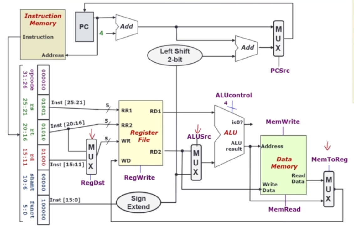
Identified Control Signals
| Control Signal | Execution Stage | Purpose |
|---|---|---|
| RegDst | Decode/ Operand Fetch | Select the destination register number |
| RegWrite | Decode/ Operand Fetch RegWrite | Enable writing for register |
| ALUSrc | ALU | Select the 2nd operand for ALU |
| ALUcontrol | ALU | Select the operation to be performed |
| MemRead/ MemWrite | Memory | Enable reading/ writing of data memory |
| MemToReg | RegWrite | Select the result to be written back to register file |
| PCSrc | Memory/ RegWrite | Select the next PC value |
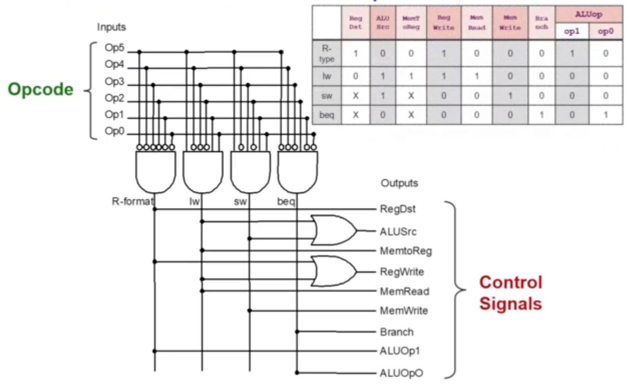
Generating Control Signals
Generally, the control signals are generated based on the instruction to be executed.
- e.g. R-Format →
RegDst= 1 We want to design a combinational circuit to generate these signals based on Opcode and (possibly) Function code - A control unit is needed!
- See The Control Unit
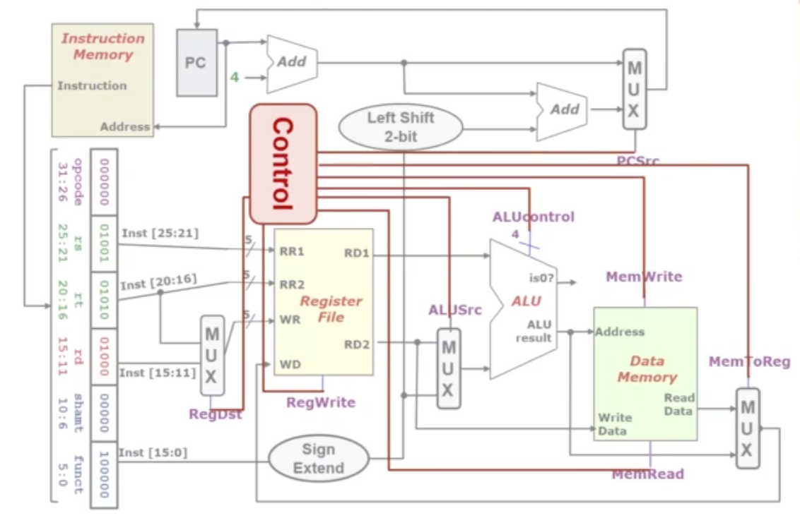
The Control Unit
- Generate all the signals!
- Based on opcode and (optionally) funct
Control Signals
RegDst
- False (0): Write Register = Inst[20:16]
- True (1): Write Register = Inst[15:11]
RegWrite
- False (0): No register write
- True (1): New value will be written
ALUSrc
Select second operand for the ALU
- False (0): Operand2 = Register Read Data 2
- True (1): Operand2 = SignExt(Inst[15:0])
MemRead
- False (0): Not performing memory read access
- True (1): Read memory using Address
MemWrite
- False (0): Not performing memory write operation
- True (1): memory[Address] ← Register Read Data 2
- Data is written into the address that is given
MemToReg
- False (0): Register write data = Memory read data
- True (1): Register write data = ALU result
PCSrc
- Also uses information from
isZeroisZero= 0 if branch are not equalisZero= 1 if branch are equal
- Also relies on opcode of branch instruction -
beq/bne BranchANDisZero
| Branch | isZero | PCSrc |
|---|---|---|
| 0 | 0 | 0 |
| 1 | 0 | 0 |
| 0 | 1 | 0 |
| 1 | 1 | 1 |
- False (0): Next PC = PC + 4
- True (1): Next PC = SignExt(Inst[15:0]) << 2 + (PC + 4)
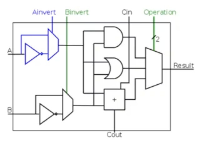
ALU Control Signal
- the most challenging control signal!
- the ALU is a combinational circuit
ALUcontrol
| Ainver | Binvert | Operation | Function |
|---|---|---|---|
| 0 | 0 | 00 | AND |
| 0 | 0 | 01 | OR |
| 0 | 0 | 10 | add |
| 0 | 1 | 10 | subtract |
| 0 | 1 | 11 | slt |
| 1 | 1 | 00 | NOR |
 |
Info
subtractis achieved using since is 2s complement
Generating ALUcontrol
Intermediate Signal: ALUop
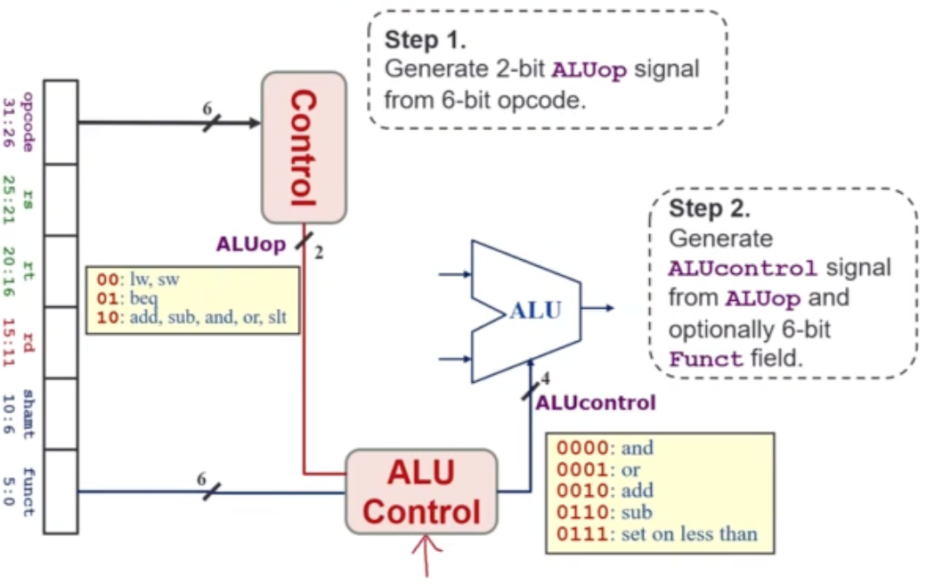
- Use Opcode to generate 2-bit
ALUopsignal- Represents the classification of the instructions
- Use
ALUopsignal (2-bit) and Function Code (6-bit) field to generate 4-bitALUcontrolsignal
| Instruction Type | ALUop |
|---|---|
| lw / sw | 00 |
| beq | 01 |
| R-type | 10 |
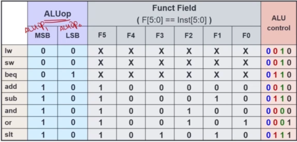 |
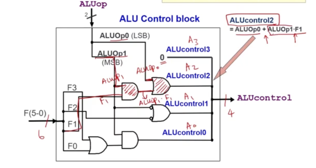
ALUcontrol
- bit 3 = 0
- bit 2 = ALUop0 1 or (F5 1 and F1 == 1)
Summary of the Combination Circuit